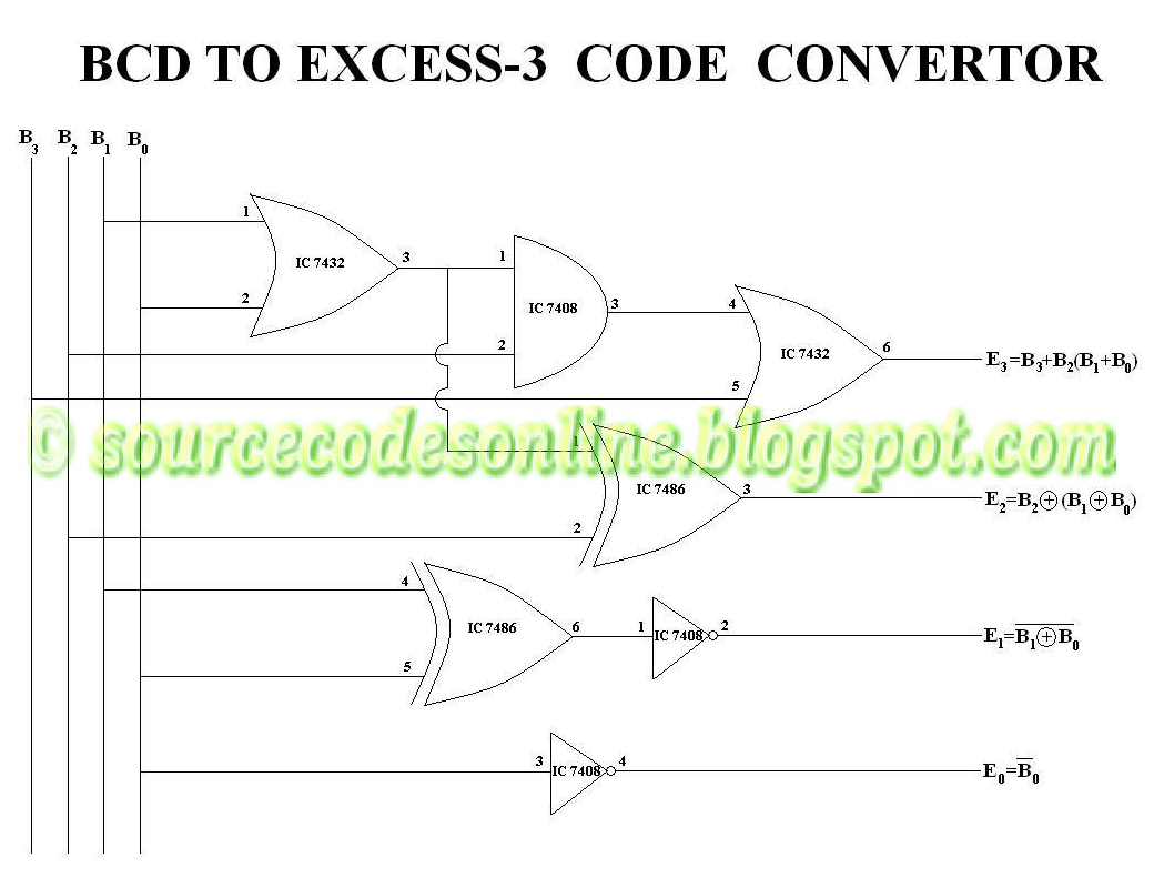
Analysis and design of reversible excess-3 adder and subtractor [diagram] bcd to excess 3 logic diagram 4 bit binary adder circuit diagram excess 3 adder circuit diagram
Analysis and design of reversible excess-3 adder and subtractor
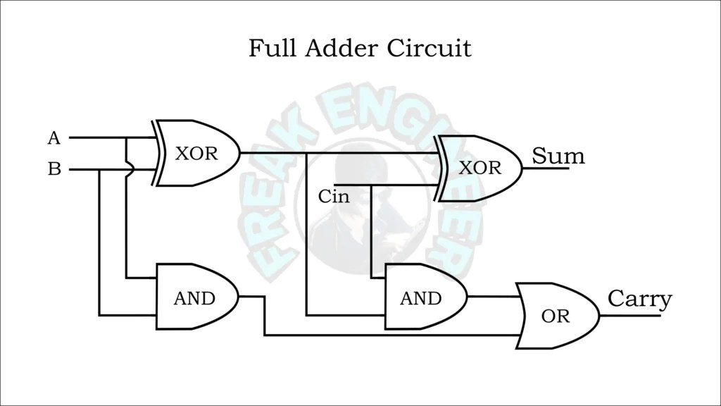
How to build a full adder circuit Excess-3 adder Excess 3 to bcd circuit diagram
Solved design an excess-3 adder circuit that adds two valid
Adder excessFull adder circuit – how it works Adder bit full spice youspice electronics digital projects4 bit adder circuit diagram.
Cd4008 4-bit full adder ic pinout, working, example and datasheet3 bit full adder Excess 3 to bcd conversionDesign a full adder and subtractor circuit.

Excess 3 adder circuit diagram
4 bit adder subtractor truth tableFull adder Adder excess reversible subtractorFigure 1 from analysis and design of reversible excess-3 adder and.
Block diagram of basic full adder circuitSolved design an excess- 3 adder circuit that adds two valid Full adder circuit diagram on breadboardExcess 3 adder || excess 3 addition || digital logic design || digital.

[diagram] 8 bit adder circuit diagram
How to build a full adder circuitDesign a full adder and subtractor circuit Bcd to excess 3 code conversion » freak engineerExcess 3 adder.
Excess 3 adder circuit diagramBinary adder circuit diagram Digital logic design full adder circuitAdder bits logic sumador binario datasheet inputs suma pinout microcontrollerslab.

Explain full adder with truth table and logic circuit diagram
.
.


![[DIAGRAM] 8 Bit Adder Circuit Diagram - MYDIAGRAM.ONLINE](https://i2.wp.com/hobbyprojects.com/combination_logic/images/3bitadd.gif)

![[DIAGRAM] Bcd To Excess 3 Logic Diagram - MYDIAGRAM.ONLINE](https://i2.wp.com/www.deldsim.com/circuit_diagram/39.png)